This is the second part of the complete test tube photometer building instructions: The building and wiring instructions. But if you want you can go back to the the shopping list. Here you find instructions for building the test tube photometer. If something is not completely clear to you, let us know and we will help you!
Build the measuring cell
-
Assemble the housing
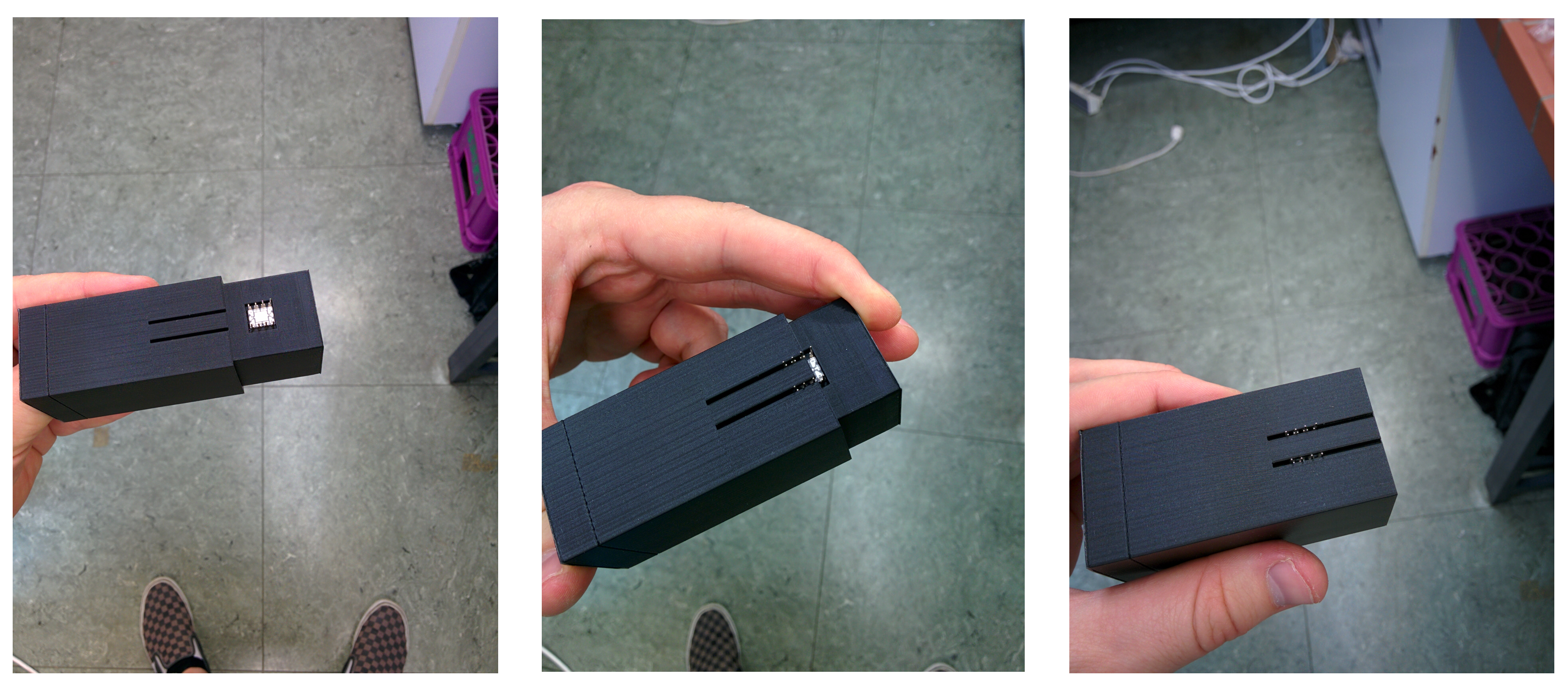
The housing consists out of two parts, the main body and a sleeve. There are two respective holes in the main body in which you can place the sensor and the LED. Slowly pull the sleeve over the main body with the LED and Sensor pins sticking out (see picture above). Please remember the sensor orientation for the correct wiring of the pins! -
Wiring
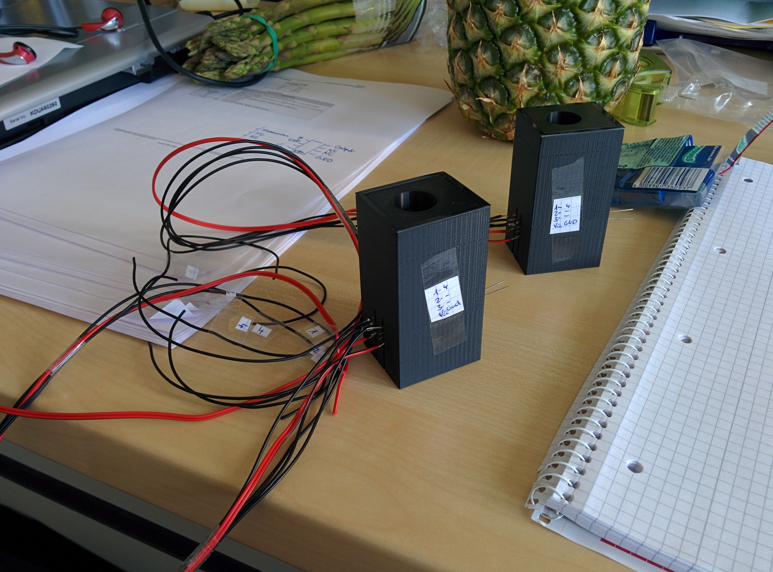
Now you can start and solder wires to the sensor an LED pins. If you have problems soldering the sensor pins with the housing assembled you can remove the sensor, solder the wires and then assemble the housing. But then you might have to use some force to fit the soldered pins through the gaps. I labeled each wire to make it easier for me to connect them later.
You should end up with five wires from the sensor:- Power (V, pin 1)
- Input/Additional Feedback (-In, pin 2)
- Power/Ground (-V, pin 3)
- Output (Output, pin 5)
- Input/Ground (Common, pin 8)
Connect it to the microcontroller
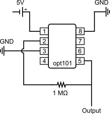
Connect sensor pin 1 to 5V, pin 3 and 8 to ground. Sensor pin is connected to pin 5 with a 1 MΩ resistor in between (see circuit diagram on the right). You can now connect the sensor output (pin 5) to any analog input pin of your microcontroller and you are ready to measure light.
 Speaking of light, you still have to connect the LED with one of the digital output pins of the microcontroller to switch the light on and off.
Well, that’s basically all you need to do to use your test tube photometer. If you like you can connect an LCD display to the microcontroller to display the measured values directly. I connected my photometer to a Raspberry Pi and let them communicate via the serial connection. The microcontroller runs this script and sends the data to the Pi which calculates the OD with this python script and writes everything to a .csv file.